W. Robert J. Funnell
Dept. BioMedical Engineering, McGill University
| Type of differential equations | Example | |
|---|---|---|
| Lumped systems | Ordinary | R-L-C circuits |
| Distributed systems | Partial | Electromagnetic fields |
In a ‘lumped’ model, the system characteristics are lumped into idealized discrete components with no (or negligible) spatial extent.
The only differentiation is with respect to time.
There is a well-developed theory for lumped-circuit analysis, originally developed for electrical circuits.
The foundations are

The basic components are linear and time-invariant:
There are also voltage sources, current sources and transformers.
The components can also be nonlinear and/or time-varying.
Analogies among electrical, mechanical & acoustical circuits:
| Electrical | Mechanical | Acoustical | |||||||||||||||
|---|---|---|---|---|---|---|---|---|---|---|---|---|---|---|---|---|---|
| v | voltage | f | force | p | pressure | ||||||||||||
| i | current | u | velocity | U | volume velocity | ||||||||||||
| R | resistance | R | resistance | R | resistance | ||||||||||||
| L | inductance | m | mass | M | mass | ||||||||||||
| C | capacitance | 1/k | compliance (spring) | C | compliance (volume) | ||||||||||||
| v = iR | f = Ru | p = RU | |||||||||||||||
| v = L di/dt | f = m du/dt | p = M dU/dt | |||||||||||||||
|
|
| |||||||||||||||
Transformers are required to convert between different domains in a circuit
model.
| Electrical | Mechanical | Acoustical |
|---|---|---|
| voltage | force | pressure |
| current | velocity | vol. velocity |
| resistor | dashpot | mesh |
| inductor | mass | tube |
| capacitor | spring | volume |
Why does one circuit seem to be in parallel while the other two are in series?
In an electrical circuit, which is easier to measure: voltage or current?
In a mechanical circuit, which is easier to measure: force or velocity?
The electrical/mechanical analogy is sometimes made the other way around, by associating voltage with velocity rather than with force, and current with force rather than with velocity. The electrical/acoustical analogy may also be inverted.
There are advantages and disadvantages to both methods, and in fact the whole issue is more complicated than it first appears.
References:
In real life, circuit components are not ideal, e.g.,
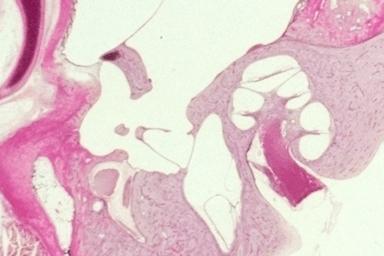
The middle ear lies between the external ear canal and the cochlea.
The middle ear includes
The middle ear also contains
Block diagram of middle-ear model
This block diagram, and the circuit model that we shall develop from it, apply
equally well to human, cat and guinea-pig middle ears.
How to model the air cavities?
Represent air cavities by C's.
Represent passage between cavities by R & L.
How to model ear canal?
Represent volume by capacitor.
This assumes that the input pressure and volume velocity are measured
close to the eardrum.
How to model the malleus and incus?
Assume that they're fixed together.

Represent malleus/incus complex by R-L-C.
How to model the eardrum?
Conceptually divide it into 2 regions, à la Békésy.
Use one R-L-C branch for part of eardrum tightly coupled to malleus,
and a second branch for the part which shunts energy directly to
the cavities.
How to model the stapes and cochlea?

Represent stapes and cochlea each by R-L-C.
Ignore incudostapedial joint and many other things.
If experimental data consist of input impedance measurements, which components can be distinguished?
Combine
components which cannot be distinguished.
 Variable elements.
There are now 11 model parameters.
 Independently determine as many model parameters as possible.
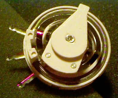
This is a silicone-rubber casting of the air cavities of a guinea-pig middle
ear. Measuring the
cavity volumes gives us Ce, Cb1 and Cb2.
 Estimate some model parameters by comparison with impedance
measured with eardrum removed.
Estimate some model parameters by comparison with impedance
measured with eardrum removed.
 Estimate remaining model parameters by comparison with impedance
of intact ear.
Estimate remaining model parameters by comparison with impedance
of intact ear.
Lack of direct connection between parameter values and anatomical or physiological properties. For example:
R. Funnell Last modified: Sat, 2005 Feb 5 18:03:57
Equations converted from TEX to HTML by TTH. I have seen the equations show up properly under Windows using Mozilla 1.7, Firefox 1.0, Netscape 4 & 7, and IE 5 & 6. They do not show up properly for me under Windows using Netscape 6.2, nor under GNU/Linux using Mozilla 1.0.