 3D Slicer3D Slicer
Download the latest stable release of
3D Slicer from the
Slicer site.
It has an open-source licence.
Install the software.
For example, under MS Windows 10, download and run the
installer (e.g., Slicer-4.11.20210226-win-amd64.exe).
By default it will be installed under AppData\Local
rather than in the usual Program Files.
The Web site includes good documentation and tutorials, although it is sometimes hard to find details about simple things. There are over 100 modules to choose from for various kinds of operations. The discussion forum is quite active and the developers are responsive. Release notes are available.
They don’t seem to be able to decide whether the programme is called 3D Slicer, 3DSlicer or just Slicer. It is not to be confused with Slic3r for 3D printing.
If you get an error message, you can see the details in the error log
by clicking on the error-log icon ![]() in the lower-right corner of the Slicer window, or by selecting
. The message texts may
disappear off the edge of the error-log window but you can see the
full text of a message by clicking on it.
in the lower-right corner of the Slicer window, or by selecting
. The message texts may
disappear off the edge of the error-log window but you can see the
full text of a message by clicking on it.
DICOM is a file format that is commonly used for medical imaging.
3-D rotation is awkward because it is not possible to rotate the scene around an axis perpendicular to the screen.
Do
(or select in the
module) and select one
of the datasets. I suggest CTA Abdomen.
In the default display layout, three orthogonal slices through the
image volume are displayed in three separate panels. A fourth panel is
a 3-D view. To display the slices in that view as well,
within each 2-D panel hover with the mouse over the tiny
push-pin icon ![]() in the upper
left corner of the panel and, in the set of icons that pops up, click on the
closed-eyelid icon
in the upper
left corner of the panel and, in the set of icons that pops up, click on the
closed-eyelid icon
![]() .
It turns into an open eye
.
It turns into an open eye
![]() and the image slice appears in the 3-D panel.
The slice may not be visible until you rotate the 3-D view.
and the image slice appears in the 3-D panel.
The slice may not be visible until you rotate the 3-D view.
In each 2-D panel, play with your mouse’s scroll wheel, and with the slider at the top of the panel.
From the dropdown list of modules on the toolbar, select . Since version 5.0, this module is found under Legacy ► Segmentation.
To ‘create and place’ a seed point for the
algorithm, click on the arrow-and-red-blob
‘Fiducial’
icon ![]() in the toolbar at the top and then
click on a location in the image.
A numbered marker will be displayed
at the location.
(If you don’t see the icon, try making your
Slicer window wider, to allow more space for the icons.
If you still don't see the icon, do
and make sure
is checked, and again
try widening the Slicer window if necessary.
If you still don't see the icon, do
and check the box
.)
(The icon is confusingly described as ‘an arrow pointing to a
sphere fiducial’ – the arrow points away from the red
blob, and ‘fiducial points’ normally refers to markers
used for alignment, not to seed points.)
in the toolbar at the top and then
click on a location in the image.
A numbered marker will be displayed
at the location.
(If you don’t see the icon, try making your
Slicer window wider, to allow more space for the icons.
If you still don't see the icon, do
and make sure
is checked, and again
try widening the Slicer window if necessary.
If you still don't see the icon, do
and check the box
.)
(The icon is confusingly described as ‘an arrow pointing to a
sphere fiducial’ – the arrow points away from the red
blob, and ‘fiducial points’ normally refers to markers
used for alignment, not to seed points.)
When a first seed point is created, it is added to a new list of
seed points, obscurely named F. In
the panel, click on
the dropdown list and
select as the current list of seeds.
In the panel, click on the
dropdown list and select
the name of the dataset that you are using. Then click on the
dropdown list and select
;
the default volume name will be Output Volume.
Click on . If you’re lucky, there will be a few seconds of processing and then the segmented region will be highlighted in the displayed images.
If the segmentation doesn’t include enough, you can define additional seed points by repeatedly clicking on the Fiducial icon and then clicking in the images. Alternatively, you can click on the small triangle beside the icon and select in the drop-down list – if the attribute has a checkmark beside it, you can click once on the arrow-and-blob icon and then click repeatedly in the images to create multiple seed points. Click on again to rerun the region-growing segmentation algorithm.
You can use the module to edit the list of seed points, removing some if you got too much or adding some if you didn’t get enough.
You can also increase or decrease the amount included in the segmented region by increasing or decreasing
Work on getting a segmentation that looks as though it could represent some fairly localized internal structure.
See the documentation for more information.
Select the module . In the section make sure the ‘volume’ corresponding to your segmentation is selected as the . For select . Make sure the box is checked (or specify the labels in the section). Click on . If you’re lucky, after some processing a 3-D surface model will appear in the 3-D section of the display. You may want to close the eye icons.
Note that there are a lot of parameters that can be played with in an attempt to improve the model, with varying degrees of loss of control.
To switch between perspective and orthographic views of the model,
hover with the mouse over the tiny
push-pin icon in the upper
left corner of the panel and, in the set of icons that pops up,
alternate between the perspective
![]() and
orthographic
and
orthographic
![]() icons.
icons.
Slicer doesn’t seem to be able to export the model in VRML format.
The module can be fun to play with. Select the desired Volume and make sure the eye icon beside the selector is open. There are many many parameters that can be adjusted, as well as some preset sets of settings like and . For example, try the CTChest sample data with the CT-Bone preset. Make sure the eye icon beside is open. The 3-D images are impressive at first glance but actually contain a lot of junk.
Note that this volume rendering has nothing to do with the model resulting from the region-growing segmentation above. You can turn off the eye icon to see that model again.
Use to save things like lists of region-growing seed points and results of segmentations. The button in the dialogue can be used to change the directories for all of the file types at once.
Slicer has tools for many other tasks, including image filtering, registration and quantification, mesh generation, and specialized applications like image-guided therapy and endoscopy. These tools are ‘for research purposes only’ and have not been approved for clinical use.
Slicer contains a number of modules for automatic image segmentation, including
GeoSlicer ‘is a software platform for digital rock visualization and image processing, encompassing multiple approaches involving thin section, CT and mCT imagery’ for the oil industry (refs 1, 2).
See Data Loading and Saving. Supported formats include the following, among others:
.nrrd: images
(including ‘segmentations’ as label images)
.h5: transforms in ITK HDF format
.mkp.json: markups (point list, etc.)
.obj, .vtk: model meshes (surface or volume)
.mrml: scene
(‘medical reality markup language’) in XML format,
containing plain-text metadata and pointers to external data files
In these notes I don’t consider the use of the DICOM format.
SlicerMorph extension.
path/jpg/%02d.jpg
for files named 01.jpg, 02.jpg, …
in subdirectory jpg/;
click on to display a list
of the included files.
jpg/)
.nrrd file.
MRML is effectively Slicer's ‘native’ file format, and
it can be saved using
.
That saves everything
related to the current ‘scene’ by creating
a .mrml file
as well as separate files
(pointed to from within the .mrml file)
that contain specific components of the scene definition
(e.g., volumes as .nrrd, transforms as .h5,
and markups as .mkp.json). A
dialogue box provides control over what, where and how things are saved.
The default name for the .mrml file is
yyyy-mm-dd-Scene.mrml.
Individual components (e.g., a volume) can be exported by going to the tab in the module, right-clicking on the component, and selected .
For our newborn CT scans, for example,
the .nrrd file corresponding
to the original .jpg images should be kept in the same
directory as the .tr3 file for that scan.
That .nrrd can later be read in using
.
After making changes (e.g., by adding a transform or markups),
the entire scene can be stored in a meaningfully named subdirectory.
In Slicer, all of the data to be processed needs to be loaded into memory. (Fiji, for example, allows ‘virtual stacks’ that are larger than memory.) Slicer offers a work-around using the ImageStacks module in SlicerMorph.
Markups include point lists, lines, etc. Here we focus on points.
In the section of the Markups module, the display size of the points can be adjusted using the field, measured either in mm if the button is pressed (i.e., grey) or as a percent relative to the screen size if it is not pressed. The two types of setting are independent of one another.
There are multiple ways to create transforms and apply them to nodes.
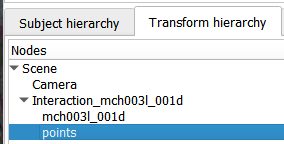
To apply a transform to multiple components
(e.g., both a volume and its markups),
in the of the
module, drag the desired components
so they are all underneath the transform.
The Resample Scalar Volume is considered to be a Legacy module.
At
More efficient resampling (2021 Sep),
lassoan
recommended the Volume Reslice Driver module in the SlicerIGT extension.
(Click on in the
Welcome to Slicer module.)
Installing that extension brings in the dependency SlicerIGSIO,
a utility extension.
The extension’s modules are listed under IGT in
Slicer’s list of modules. Help on using the module is at
www.slicerigt.org.
The following is an attempt to follow the tutorial
SlicerIGT_HandsOn_2015-1--05.pptx
at the link given at
www.slicerigt.org/wp/user-tutorials/,
starting at slide 17.
At
Reslice dicom data given computed axis (2023 Sep),
pieper suggested the
Resample Scalar/Vector/DWI Volume module
for image and vector-image resampling.
In the
list of modules it’s listed under
Converters but I couldn’t find it in the list of modules
in Slicer 5.6.1.
There is documentation at
Modules:ResampleScalarVectorDWIVolume-Documentation-3.6, where it
is said to be under Filtering.
Its Module Type is CLI:
‘CLI modules are Python scripts or command-line applications that do not rely on Slicer’
(ref).
At
Non Orthogonal reslice (2024 Jul)
pieper suggested
the CropVolume module.
See also
Resample image volume along user-defined plane (2024 Jul), where
lassoan
points to code to
Extract slice from volume,
which uses module resamplescalarvectordwivolume.
Before trying to use the code in the Python console
():
myStorageNode = sliceImageNode.CreateDefaultStorageNode()
myStorageNode.SetFileName("c:/tmp/something.nrrd")
myStorageNode.WriteData(sliceImageNode)
To use module resamplescalarvectordwivolume in the GUI:
Subject hierarchy of the Data module)
causes the 4×4 transform matrix to be displayed, where
the ai,j
specify the rotation and/or scaling,
and the ti specify the translation.Data module, right-click in the
column of the node for your volume,
and check the box.
That creates a transform node for your data node,
and creates an Output Volume node.
Data module,
right click on the output volume, and select
.
Data module and select
.
A file with a name of the form Interaction_name.h5
will be created. That file will contain an array
TransformParameters of length 12..h5 file will also contain an array
TransformFixedParameters of length 3;
it seems to correspond to the centre of the volume:
((npix−1)×mm/pix) ÷ 2
minus any translation that has been applied.